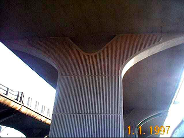
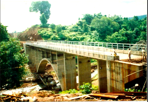
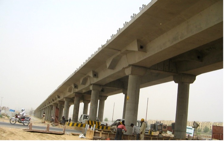
Historically, most masonry or reinforced concrete bridges have been of monolithic construction. The entry of structural steel for bridges was made feasible by providing bearings. For prestressed concrete bridges also, bearings became a necessity for accommodating creep, shrinkage, and thermal movements. A recent survey conducted in New Zealand concluded that old reinforced concrete bridges performed much better during earthquakes as compared to those with bearings. However, simply supported bridges resting on bearings have remained very popular because of their utter simplicity. Standard designs can be used for such bridges.
Embodied Carbon Footprints of Bridges with Monolithic Piers: Indian Experience
Dr Vasudev V Nori
Abstract
It has now become apparent that a need for retrofitting old bridges was due to the damage caused to the bearings (caused by rainwater leakage at expansion joints). This led to more sophisticated expansion joints and bearings. It has been said that “No joint is the best joint”. The present article deals with our experience of bridges with monolithic piers. Such bridges are certainly more difficult to design and construct. But these are virtually maintenance-free, elegant, and have much superior resistance to seismic loads. The article includes embodied carbon footprint calculations, considering the main materials of construction. The average embodied carbon footprint value of 473 kgCO2e/m2 seems encouraging. Since such bridges consume less concrete and steel, they could be more sustainable.
Keywords: Concrete Bridges; Monolithic Construction; Maintenance; Sustainability.
This paper was published in the Jan-Mar 2023 issue (Vol 13, No. 1) of Structural Engineering Digest (SED) published by the Indian Association of Structural Engineers (IASE). This is being re-published in LCCF Newsletter for wider dissemination with due permissions, both from SED-IASE and also from the authors.
Introduction
Most of the distress observed in bridges constructed during the last fifty years emanates from the expansion joints and bearings. Unsatisfactory performance of expansion joints results in ingress of rain water causing damage both to the structure and to the bearings. It became necessary to detail these joints so that adequate space is available for maintenance and replacement of bearings. During earthquakes it has been found that girders some times get dislodged from bearings. The latest amendments to the Indian Road Congress Codes require that positive measures such as restrainers be provided so that girders do not get dislodged during earthquakes.
Simply supported girders resting on bearings are very popular because these structures are simple to design and to execute. The substructure design is also greatly simplified because of determinate nature of the structure. It is true that there are situations where bearings/simply supported spans/expansion joints cannot be altogether avoided for large span bridges with well foundations. On the other hand monolithic joints and redundancy of the structural system do result in savings in the cost of construction and maintenance. Elimination of bearings improves the structural performance during earthquakes. Finally integral form of construction will require much lesser inspection and maintenance efforts.
The article includes selected cases of integral-type of bridges/flyovers which have been constructed during the past 4-5 decades and are well documented (references 1 to 6). Besides providing a brief description of these bridges/flyovers, an attempt is also made to calculate the carbon footprints of the main construction materials i.e. cement concrete, reinforcing steel and prestressing steel which have been used during construction of these bridges/flyovers. It was quite a difficult task to search old records of material quantities; however, with strenuous efforts, the author was successful in obtaining the same. The carbon footprint calculations also require global warming potential (GWP) values of the materials used in construction. Not much work has been done in India to evaluable the GWP of different construction materials, excepting the lone effort done by the International Finance Corporation (IFC) in 2017. We have used the values from the draft database created by the IFC in consultation with a number of manufacturers, suppliers and developers from India.(source: ‘India Construction Materials Database of Embodied Energy and Global Warming Potential’, Methodology Report, International Finance Corporation in partnership with European Union, 2017)).
Flyover at Trombay (1978-1979)
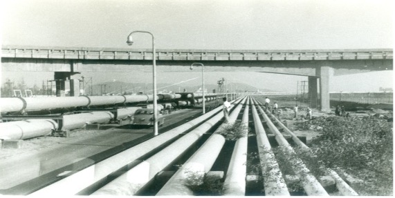
This is a 465-m long two-lane flyover that provides a direct link between two thermal power stations. These thermal stations are separated by Bombay Port Trust Road, a drainage channel, and several large above-ground pipelines. In the plan, the flyover is on a 900 curve. The carriageway width is 7.5 m increasing to 8.5 m for the circular spans. The foundations consist of precast pre-bored concrete piles installed at a batter of 1 in 7. The piles are octagonal in shape with a diameter of 408-mm and their length varied between 8 and 12m.
More information on the design and construction on the flyover is available in a paper at Reference 1
Road over bridge at Nerul (1985-1987)
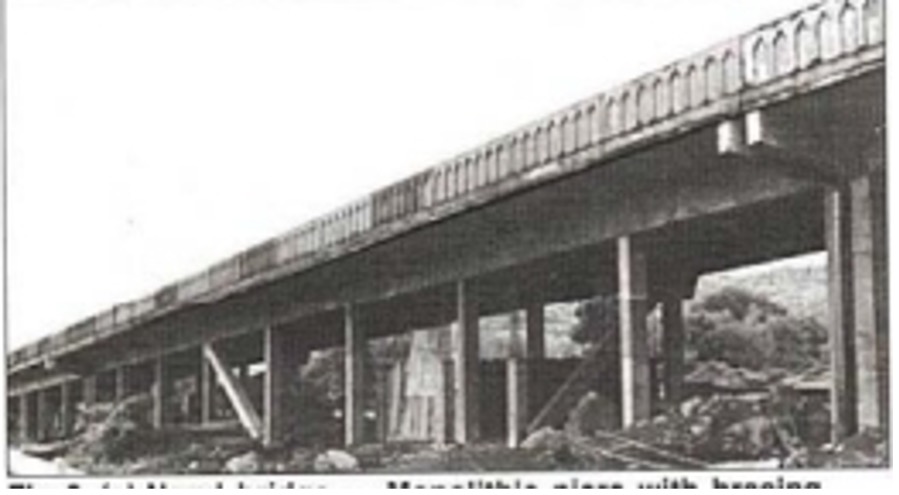
Constructed in 1987s the viaduct is about 420-m long. The carriageway of the bridge is 26.70-m wide constructed in two phases. After diverting the traffic from the completed first phase, the second phase was taken up. The 13.5-m wide carriageway for each phase is supported on two reinforced concrete continuous girders without any cross girders. Expansion joints are spaced at about 78m.

Another unusual future of this bridge is the structural system for resisting horizontal loads. Uneven pier heights in the longitudinal direction result uneven in piers. Uniform pier sizes must be maintained for aesthetic and construction reasons. More information on the design and construction on the flyover is available in a paper at Reference 2.
Low-level flyover at Dadar (1993)
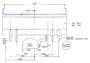
Constructed on a design and construct basis this low-level flyover is 385-m long. The flyover had to be constructed in a very congested area over a road with a number of services running underneath which include a major storm water drain and an 1800 Ø water supply pipe besides other small diameter sewers and other utilities. The utilities do not run parallel to the axis of the bridge. The exact location of these services was not available at the time of the invitation of bids on a design and construct basis.
The proposed solution consists of a 600-mm thick solid slab supported on wall piers with expansion joints spaced at about 54m. Reduction in structural depth resulted in a reduction in the length of the flyover. The wall piers are 250-mm thick and supported on 400-mm diameter driven piles. The pier functioned also as a deep girder transferring the vertical reaction to the piles. The solution was such that the piles could be located so that services remained undisturbed. More information on the design and construction on the flyover is available in a paper at Reference 3.
Road over bridge at Madgaon
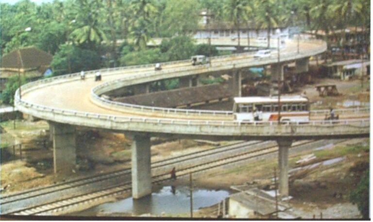
Constructed in 1996 this bridge is about 640-m long. The carriageway is to cater to two lanes of vehicular traffic. One of the unusual features of this bridge was restrictions on the approach ramps. One of the ramps had to be located within the railway property. This resulted in a road over a bridge whose alignment consisted of a variety of horizontal and vertical curves. Semi-integral construction with monolithic piers permitted slender piers with variable spacing to suit the alignment. More information on the design and construction on the flyover is available in a paper at Reference 3.
Road over bridge at Khandeshwar
Completed in 1999 road over bridge at Khandeshwar crosses two existing railway tracks and two future tracks. The length of the road over bridges is about 645-m long. The twin carriageway is separated by a 6-m gap. The structure has been so designed that this gap could be bridged for extending the carriageway in the future. More information on the design and construction on the flyover is available in a paper at Reference 3.
Road over bridges in Jharkhand with continuous spans and monolithic piers
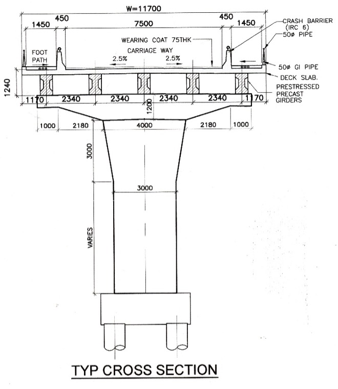
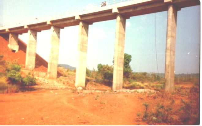
Konkan Railway Corporation Limited undertook the task of constructing 14 road over bridges in Jharkhand. All bridges are continuous with monolithic piers. The slenderness of the piers appears surprising at a first glance because the layman is used to seeing massive piers and pier caps with simply supported girders. For the integral form of construction to be feasible, piers have to be necessarily slender even if heavily reinforced. The lengths of individual bridges vary depending on the availability of land. (the maximum length was about 320 m). Approaches are in reinforced earth. These are excluded in the study.
The width of the carriageway of most of the bridges is 11.70 m. The bridges generally cater to two lanes of vehicular traffic with 1.5-m wide footpaths on either side. The carriageway is supported on five 1-m deep precast post-tensioned girders for 15 m spans and a 240-mm thick reinforced concrete deck slab which is cast-in-situ. At track crossings where 20m spans are required the girder depth is 1.20 m. Continuity of the bridges in the longitudinal direction is achieved by providing non-tensioned reinforcement in the deck slab. All the bridges are located on a curved alignment.
Because curved spans have to be built using straight precast girders the span length was restricted to 15m. Where the curves were sharp, the width of the carriageway was increased. In some cases, the number of girders was increased so that the girder cross-section could be retained for all spans. The girder length was adjusted to suit the radius of curvature. More information on the design and construction on the flyover is available in a paper at Reference 4.
Rail over bridge at Ghatshila Galudi
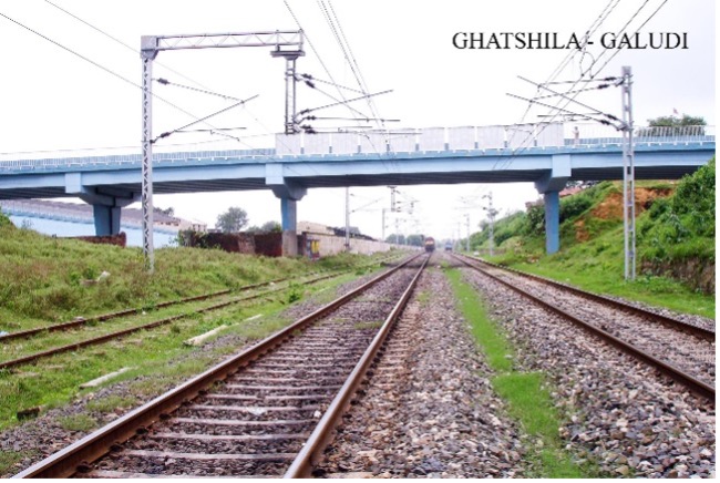
An integral form of construction using precast post-tensioned I girders does offer optimum solutions for the bridges, both from the consideration of construction cost and from aesthetic considerations. These benefits outweigh the additional efforts needed in analysing and designing these structures which are certainly more complex than the conventional bridge structures with simply supported spans on bearings. It is expected that in the long run these bridges will require lesser maintenance and are expected to perform better during earthquakes.
Reinforced concrete rail bridges for KRCL
Konkan Railway Corporation Limited (KRCL) evolved its own standard designs for a variety of spans, and spill-through abutments in view of a very tight construction schedule. There were, however, situations where standard designs are not ideally suited either because of the remoteness of sites or because of peculiar site conditions. The following bridges are some typical examples of bridges with monolithic piers. These are not spectacular in terms of size but are nevertheless unique in their own way. All these bridges have been designed so that they are cost-effective, aesthetically pleasing, easy to construct, and require minimum maintenance.
Road under bridges for embankments up to 12-m in height
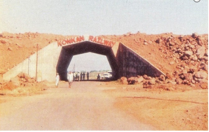
The track above runs 10 to 12m above ground level. The standard design for this type of design would have been a plain concrete abutment supporting a reinforced concrete deck. This results in two expansion joints and bearings which require regular inspection and maintenance. The proposed solution comprises of a polygonal vault in reinforced concrete and founded at shallow depths on hard laterite. The profile of the portal is such that symmetrical loads due to earth fill cause small bending moments. For ease of construction, a polygonal profile was preferred to a circular or parabolic vault. The presence of axial force in the portal improves structural efficiency. The clear span of the vault is 11.50 m. The clear height of the vault is 7m at the crown. A minimum headroom of 6.0m is available for the 7.5m carriageway. The vault thickness is 0.675m. Such vaults have been constructed at several locations. (Modified at times with a skew crossing,(see picture below) or with unsymmetrical retention of earth. More information on the design and construction on the flyover is available in a paper at Reference 5.
Nullah crossings with high embankments and continuous portal bridges
KRCL Standard designs in such cases comprised 20-m simply supported pre-cast post-tensioned cross girders resting on circular reinforced concrete piers with spill-through abutments. The pre-cast pre-stressed girders were to be cast on the completed embankment. Consequently, the casting of prestressed girders could begin only after the completion of the embankment. Because the deck is simply supported there is an expansion joint on each pier. At some locations, nullah crossings were barely 20-m wide but with embankments as high as 20m the bridge had to be much longer. The nullahs would be dry most of the time but subjected to flash floods during monsoon. Scouring is rarely a problem at most locations because the bed is rocky.
Because of insufficient repetition, precast pre-stressed girders were proving to be costly at these sites. The spill-through abutments consist of twin rectangular columns. These are provided with inclined struts which get eventually buried in the embankment. Consequently, the longitudinal forces are resisted by truss action with negligible bending moments. This has resulted in a very efficient structural system. The piers are 3m wide and 750 mm thick with semi-circular returns. At another site, the formation was 22-m above the bed level. The pier thickness was increased. Six similar bridges were constructed. The deck consists of a flat beam 3-m wide and -m deep supporting a 5.7-m wide spanning 10 m and monolithic with flat piers. The deck is in M30-grade concrete. More information on the design and construction on the flyover is available in a paper at Reference 5.
Nandivali stiffened arch bridge
At this site, the track emerges from a tunnel to cross the Nandivali nullah. The nullah is practically dry or at the most about 6m wide during the dry season. During floods, however, the nullah may have water depths up to 4.5m. At high flood, the nullah is almost 40m wide at the crossing. A continuous frame structure was not suitable at this site especially since in the central 30-m sound founding strata was not available at shallow depths.
The proposed solution consists of a 72-m long bridge with a 36-m span stiffened arch bridge. The arch rises 9-m above springing. The approach spans are continuous portal type. The deck is 5.7-m wide with a footpath on one side. It is supported by a flat beam 3m wide and 0.9m thick.
Elevated viaduct for Delhi Metro Rail Corporation (DMRC)
The elevated viaduct and six stations in Dwarka sub city are located on a 30-m wide strip of land made available for MRTS. The elevated viaduct is required for cartering for two tracks with a centre-to-centre spacing of 4.10m. The horizontal alignment is mostly straight. The lowest radius of the curve of the alignment is 900m. The ground is reasonably level. The alignment crosses 6 major roads, one major drain, and an oil pipe corridor. The soil investigation revealed that open foundations located at about 1.8m below ground level could be adopted. The main consideration for span configuration was the clearance required for road crossings and bearing in mind that an open foundation must be used. The height of the rail varied between 7.0m to 9.0m above ground level. At a few locations, the rail level was 10.30m above ground level.
The deck cross-section consists of two 1.2-m deep voided girders with a span arrangement of 13.5m + 16.5m + 16.5m + 13.5m. The deck frames are cast monolithically into circular piers of 750mm for end spans and 900mm for intermediate supports. Diaphragms at pier locations are cast-in-situ providing frame action both in transverse and longitudinal directions. The continuity of the structure over intermediate supports in the longitudinal direction is achieved by introducing prestressing cap cables at these locations. In the transverse direction, the individual deck slabs get connected by overlapping reinforcement and a cast-in-situ connection. The substructure consists of open foundations comprising of conventional isolated footings resting on medium sand. Corbels are provided for individual circular piers so that precast girders could directly rest on the corbels without any additional temporary supports. Bridges with monolithic piers can be adopted both for cast-in-situ and precast concrete structures. The slenderness of the piers combined with the elimination of pier caps and bearings enhances the visual appearance of the bridges. More information on the design and construction on the flyover is available in a paper at Reference 6.
Summary of Carbon Footprints
Table 1 provides a summary of the carbon footprints of the bridges/flyovers discussed above. It may be noted that while calculating the carbon footprints, we have considered only the carbon footprints of major materials used in construction, namely, concrete, reinforcing (black) steel, and prestressing steel, the latter being considered wherever it has been used.
In the summary, the carbon footprints per metre length and also per square metre of the plan area are also included. Leaving apart, the ROB at Jharkhand and the elevated viaduct at DMRC, which are special cases, the average value of carbon footprints for the remaining eight structures comes out as 5363 kgCO2e/m and 473 kgCO2e/m2.
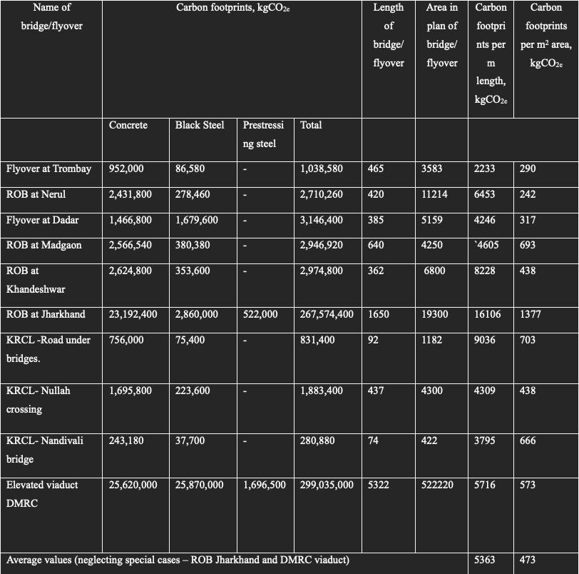
Table 1: Summary of carbon footprints of bridges/flyovers
Conclusion
Design of bridges with monolithic demands require substantially more engineering effort. Construction of such bridges demands more diligent engineering. But these bridges are virtually maintenance-free. Because of the redundancy in the structural system, they perform much better compared to bridges with simply supported spans resting on bearings. Lastly, they are elegant. As can be seen above the solutions that are evolved are site-specific. Prestressed concrete bridges should be designed considering the permissible crack-width, rather than the “no tensile stress” basis. Civil engineering construction is a team effort. The author has been fortunate to have had the opportunity to conceive the designs of these bridges. The average value of the embodied carbon footprints of 473 kgCO2e/m2 for eight bridges seems quite low. There is an urgent need to build bridges with monolithic piers. Such bridges will have much better life cycle costs.
Acknowledgement
The author is immensely grateful to clients for reposing their confidence in SPACPL, the author’s colleagues, and the Contractors’ engineers. Finally, I the author would like to express gratitude to Shirish Patel (Chairman Emeritus) for encouraging innovation.
References
- Vasudev V Nori, Narendra S Thakkar., “A flyover at Trombay”, Bridge and Structural Engineer, 10, No.4 -December 1980 .
- V.Nori., “Road overbridge at Nerul”,The Indian Concrete Journal, May 1992, pp271-273
- V.Nori, B.S.Joshi M.N. Patel., “Integral bridges: Examples from quarter century experience”, The Indian Concrete Journal, September 2005, pp 22-25
- B.Nagendra, P.H.Srinivasachar, and Haroon Shaikh.,”Road over bridges in Jharkakand with continuous spans and monolithic piers”, The Indian Concrete Journal, Report, April 2009 PP 17-21.
- C.Gupta, S.D.Limaye, M.K.Gupta, V.L.Dodeja and, V.V.Nori., “Integral Bridges on Konkan Railway”. The Indian Concrete Journal, September 2005, pp 60 -64
- Rajan Kataria, Haroon Shaikh and, V.V.Nori., “Design and construction of elevated viaduct in Dwarka City, Delhi” The Indian Concrete Journal, September 2005, pp 636-39
Authors
Dr Vasudev V Nori
Dr Vasudev V Nori, born in 1938, received his B. E. (Civil) degree from VJTI Mumbai University in 1957. He received Dr es Sciences Techniques from EPUL (now EPFL) Switzerland in 1965. He has been a lead engineer for a variety of civil engineering projects. He is presently the of Chairman Shirish Patel and Associates Consultants Private Limited, 3rd Floor Dabur House, 41-45 N Master Road Mumbai 400023.


